Development of an AMR Calibration Unit
AMR, CV, Camera Calibration, Tooling
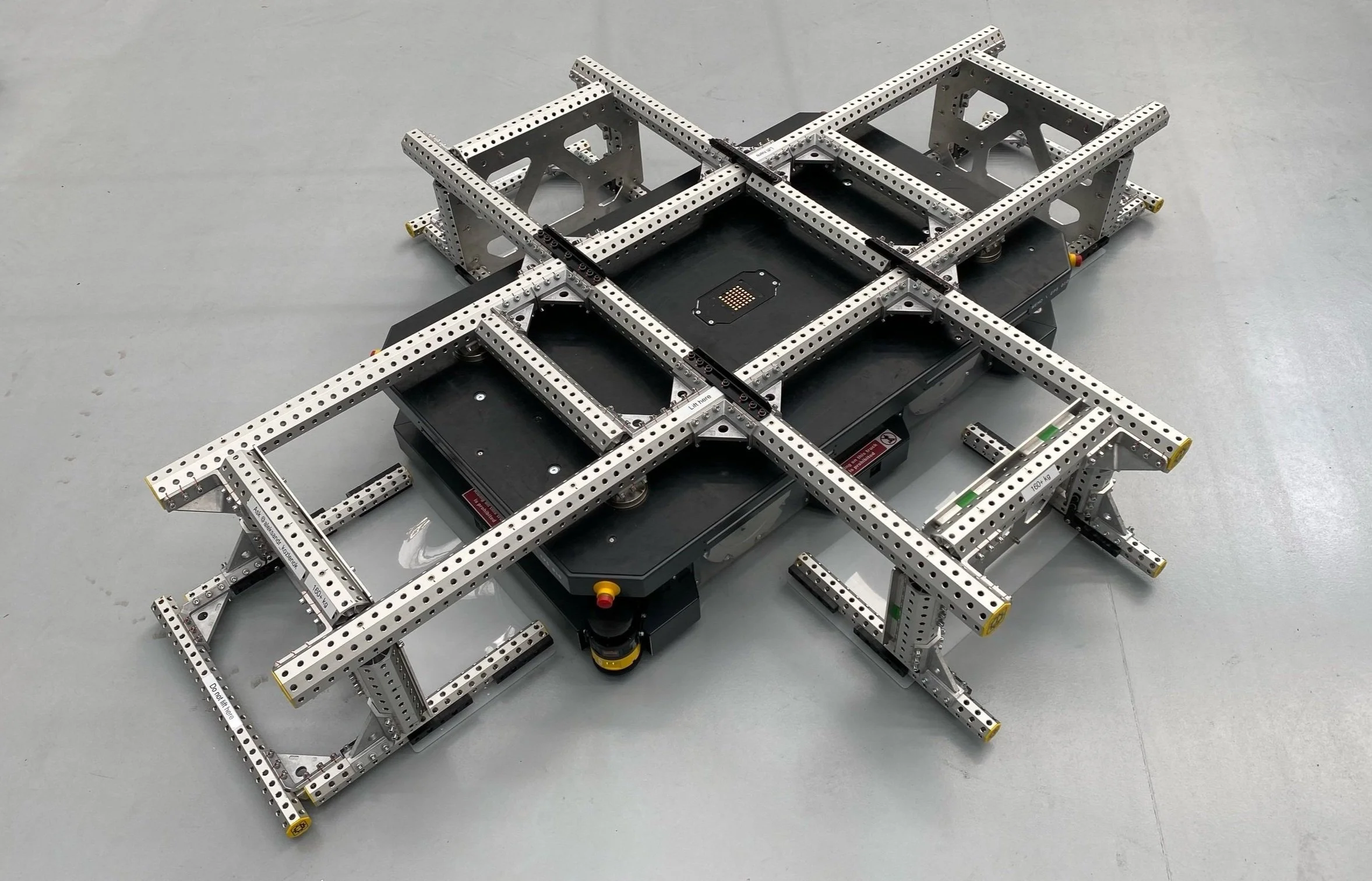
In 2022, I developed a camera calibration tool for AMRs. Establishing the positions and orientations of the cameras is crucial for localization and positioning for wheeled AMRs that utilize computer vision (CV) algorithms. To speed up the calibration process within the production batch, it was essential to have a unit that facilitates simultaneous intrinsic and extrinsic calibration of four cameras on the AMR. Additional requirements of rigidity and dimensional stability, as well as low manufacturing costs, were taken into account to ensure results repeatability and high accuracy and scaling possibilities.
Project summary
• Full ownership of the project
• Trade study
• CAD development
• Assembly and commissioning management
Responsibilities
1. Design a calibration jig with tolerance grade below IT10 (< 0,86 mm at lengths up to 3150mm)
2. Achieve geometry consistency over 10^4 calibration cycles
3. Provide uncomplicated transportation and handling (< 200 kg)
4. Provide mounting surfaces for pneumatic/mechanical lifting devices
Project objectives
Given the need for flexibility and the requirement to use available hardware (glass marker targets), I chose to divide the unit into three domains:
• Main structure (to hold target arrays and provide mechanical interfaces for lifting and logistics)
• Target arrays (to provide positioning and orientation of the marker targets)
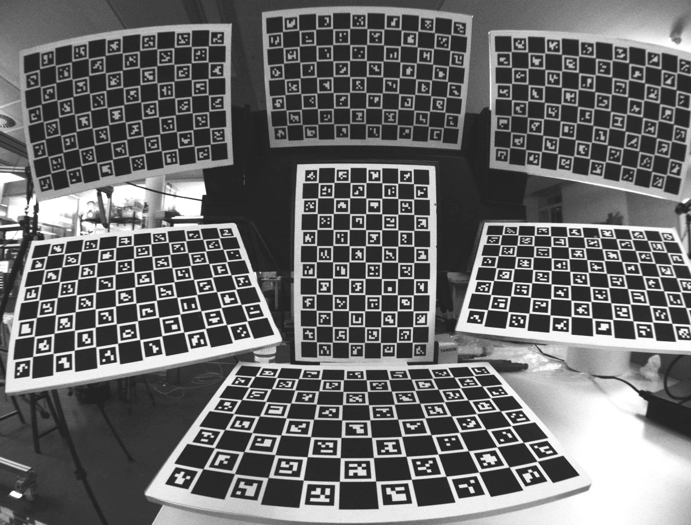
• Glass targets (to compute intrinsic parameters such as lens distortion and perspective distortion)
The dimensions and design of the target array holders were determined by the selection of the glass-laminated marker targets and the requirement to cover the entire camera field of view. The precision requirements, with a position tolerance of up to 0.05 mm on the dowel pins, restricted the manufacturing methods to high-accuracy three-axis CNC machining and high-density epoxy-based tooling boards (exceeding 800 kg/m3).
1. Concept definition and trade study
Nevertheless, selecting the design and materials for the main structure needed a thorough approach. Gathering and categorizing all design factors resulted in the trade study approach. The most weighted parameters and limitations were:
• Overal unit cost < 15000 GBP
• Main structure cost < 5000 GBP
• Target arrays positional tolerance
• Robustness
• Estimated manufacturing and delivery time
Below are the most effective solutions identified in the trade study:
According to the trade study of several materials and production methods, the Tuenkers TGT system, based on 80mm octagonal extrusions, became the optimal solution for the given requirements, timeline, and cost.
The second-best solution was an aluminum welded structure that involved post-machining using off-the-shelf (OTS) square extrusions. Although CNC surface machining provided the best possible accuracy, the overall cost exceeded the target budget, and the material used for the extrusions, due to its welding characteristics, limited the structural robustness.
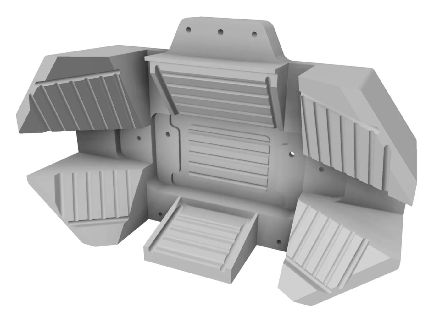
The development of the array holder focused solely on the mechanical interface with the structure and the definition of the unmated surfaces. This was possible because of the glass marker targets' predefined layout, form factor, and the array's known position.
The target array holder was designed with a high-density tooling board with two dowel pin bores on the back surface to guarantee positional tolerance. To achieve accurate bonding of the glass targets, every mating surface had several machined rows designed to stop targets from floating on the excess adhesive during application.
For weight reduction, the frontal and rear surfaces were designed with machined pockets to eliminate excess material from the part and reduce the load on the side structure joints.
2. CAD development of the calibration unit
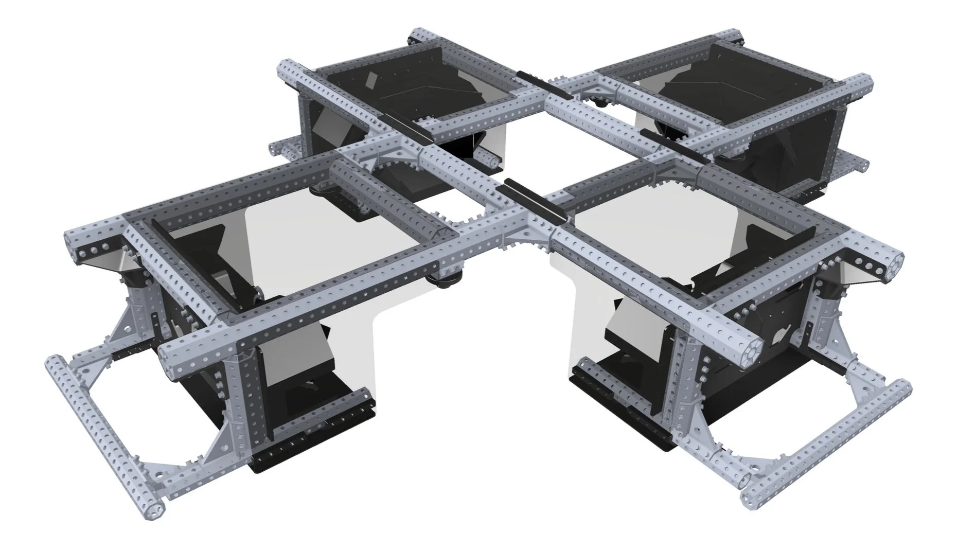
The Tuenkers TGT system concept is derived from automotive tooling. This system features octagonal beams made of high-quality aluminum, exhibiting a substantial sectional moment of inertia. Each beam is equipped with a grid of accurate bores to ensure positional precision during assembly. The TGT system has a wide range of corner nodes and joints for structural assembly, providing significant design flexibility. Additionally, the TGT system's design guarantees positional accuracy during reassembly and after transportation, along with easy access to spare parts for future main structure modifications.
I utilized jointless 2700 mm longitudinal beams to create a uniform stiffness gradient throughout the structure, along with short side beams for the lateral targets array, employing eight 90-degree joints (two for each side beam). The torque limit of the 90-degree joints, which is 125 Nm each, restricted the weight of the lateral array holders and supplementary accessories. The picture below shows that the final design incorporated two detachable side assemblies (side structures with array holders), significantly improving handling, transportation, and storage.
In addition to the main structure and target array holders, the unit required additional features such as shading panels, mechanical interfaces to the external lifting devices, and pick-up points for handling.
The required light dissipation and prevention of the reflection on the glass targets drove the shading panel's requirements. Plastic semi-transparent plexiglass panels were cut in size and bolted to the main frame to comply with the weight limitation. The mechanical interfaces of the main structure included a pin system consisting of round and diamond pins to position the tool over the AGV/AMR. Additionally, the structure facilitated mounting patches on the longitudinal beams designed to install electro-mechanical lifting pillars.
The AGV/AMR calibration unit was successfully developed within budget to accommodate a fleet of 150 robots. This system enabled simultaneous intrinsic and extrinsic calibration of the four stereo cameras mounted on the robots. As a significant project outcome, the fleet's docking accuracy improved from ±20 mm to ±8 mm, which helped reduce the duration of the vehicle's production cycle. Additionally, the intrinsic calibration algorithm improved the camera lens selection out of the batch, enhancing the accuracy and driving safety of AGVs and AMRs.
Key results
